DOI:
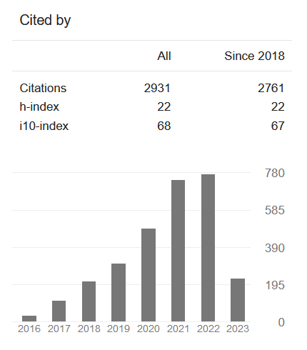
DOI: Google Scholar Analysis
For Authors


ijaems Issue
Application of High-Voltage, Precision, Low-Power Max9943/Max9944 Operational Amplifier in Industrial Process Control Using ±20ma OR 4-20ma Current-Loop Systems( Vol-2,Issue-9,September 2016 ) |
|
Author(s): Ezeilo Chibuike J, Okolo Chidiebere C, Okeke Obinna, Okoye Ngozi B, Nebechi Shadrach I |
|
Keywords: |
|
|
4-20mA current loop, micro-controller, Transmitter, Receiver, Sensors. |
|
Abstract: |
|
|
This article explains how to apply a high-voltage, high-current-drive operational amplifier to convert a voltage signal into a ±20mA or 4–20mA current signal for use in process-control industrial applications. The MAX9943 op amp a family of high-voltage amplifiers that offers precision, low drift, and low power consumption device was used as case study]. Experiments are described and test results presented. Current loops are known for their high immune to noise compare to voltage-modulated signals, a feature that makes it ideal for use in a noisy industrial environment. This signal can travel over a long distance, sending or receiving information from remote locations. A current loop typically includes a sensor, transmitter, receiver, and an ADC or a micro-controller (figure 1). The sensor measures a physical parameters such as pressure or temperature and provides a corresponding output voltage. The transmitter converts the sensor’s output into a proportional 4mA-to-20mA current signal, while the receiver then converts the 4mA-to-20mA current into a voltage signal output. This receiver’s output is then received, interpreted and converts into a digital signal output by an ADC or a micro-controller. Experiment performed using the relationship the relationship stated in equation 5, shows that if the input voltage level rise above or fall below ±2.5v, the op amp device attains its saturation point and its output voltage can no longer increase. As shown in figure 3, where the curve flatten and no longer follow the ideal linearity characteristics that was supposed. |
|
Cite This Article: |
|
| Show All (MLA | APA | Chicago | Harvard | IEEE | Bibtex) | |
Share: |
|